
TPI RLY – Relays
Table of Contents
The TPI RLY block controls the relays of the AC precharge circuit of the all-in-one programmable inverter (TPI8032 22kW).
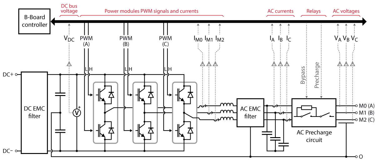
For reference, the topology of the converter is shown below. The inverter naturally acts as a diode rectifier due to the anti-parallel body diodes of the MOSFETs. Uncontrollable currents will flow through the diodes should the DC bus voltage drop below the rectified AC voltage. For this reason, it is essential to precharge the DC bus before initiating regular operation. More information can be found in TN131: DC bus precharging techniques.
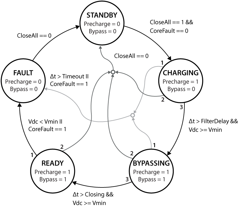
By default, the relays of the AC precharge circuit are fully automated with a Finite State Machine and allow a safe and seamless connection to the grid. Please refer to the TPI8032 datasheet for more details. Optionally, it is possible to control the precharge and bypass relays manually. By doing so, the user bears the risk of damaging the equipment in case of inadequate operation.
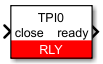
Simulink block
Signal specification
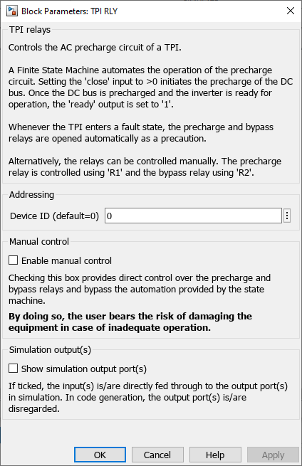
- Setting the
closeinput to >0 initiates the precharge of the DC bus. - The
readysignal is set to ‘1’ once the DC bus is precharged and the inverter is ready for operation. - When manual control is enabled, the precharge and bypass relays are controlled using
R1andR2respectively. - The
sim R1andsim R2output signals are used in simulation and documented in Simulation essentials with Simulink (PN135).
Parameters
Device IDselects which TPI to address when used in a multi-device configuration.Enable manual controlbypasses the automation provided by the state machine and provides direct control of the precharge and bypass relays.Show simulation ouput port(s)defines if the simulation output ports are displayed or not.
PLECS block
Signal specification
- Setting the
closeinput to >0 initiates the precharge of the DC bus. - The
readysignal is set to ‘1’ once the DC bus is precharged and the inverter is ready for operation. - When manual control is enabled, the precharge and bypass relays are controlled using
R1andR2respectively. - The target output ports (only visible at the atomic subsystem level) are used in simulation and documented in Simulation essentials with PLECS (PN137).

Parameters
Device IDselects which TPI to address when used in a multi-device configuration.Enable manual controlbypasses the automation provided by the state machine and provides direct control of the precharge and bypass relays.Show simulation ouput port(s)defines if the simulation output ports are displayed or not.
