Table of Contents
The Direct output PWM block sets PWM output(s) directly to ‘0’ or ‘1’.
This technique is typically used for Model Predictive Control (TN162) or Direct Torque Control (AN004).
Like the other PWM blocks, the Direct output PWM block supports dead-time generation and can be activated or deactivated. More information is available on the PWM page.
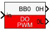
Simulink block
Signal specification
- The input
insets the PWM output to ‘1′ (in>0) or to ‘0’ (in<=0) - The input
Aallows the activation (>0) or deactivation (<=0) of the PWM output(s). - The output(s) is/are the generated PWM signal(s), according to the selected
output mode. The output(s) is/are only used in simulation.
Parameters
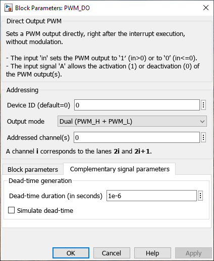
Device IDselects which B-Box/B-Board to address when used in a multi-device configuration.Output modeselects between a single PWM signal or complementary signals with a dead-time.Addressed channel(s)orAddressed lane(s)(vectorizable) selects the PWM outputs to address.Show ”activate” inputmakes theAsignal input visible. If not checked, the block is active by default.Dead-time duration: configures the dead-time duration if theOutput modeis set at Dual (PWM_H + PWM_L).
The parameters
output mode, addressed PWM, dead-time and show ”activate” input are common to all PWM blocks and are further documented on the PWM page.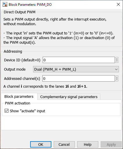
PLECS block
Signal specification
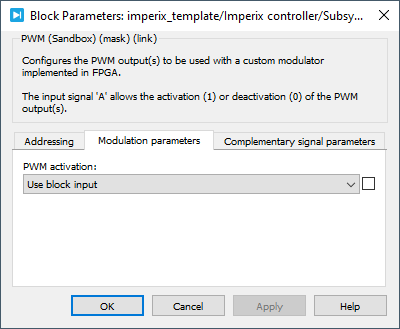
- The input
insets the PWM output to ‘1′ (in>0) or to ‘0’ (in<=0) - The input
Aallows the activation (A>0) or deactivation (A<=0) of the PWM output(s). - The target outport(s) (only visible at the atomic subsystem level) is/are the generated PWM signal(s), according to the selected
output mode. The output(s) is/are only used in simulation.

Parameters
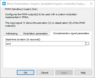
Device IDselects which B-Box/B-Board to address when used in a multi-device configuration.Output modeselects between a single PWM signal or complementary signals with a deadtime.Output lane(s)orOutput channel(s)(vectorizable) selects the PWM outputs to address.PWM activationmakes theAsignal input visible if the option “Use block input“ is selected. If not, the CB-PWM block is activated by default.Dead-time durationconfigures the dead-time duration if theOutput modeis set at Dual (PWM_H + PWM_L).
The parameters
output mode, addressed PWM, dead time and PWM activation are common to all PWM blocks and are further documented on the PWM page.
C++ functions
Functions specific to the direct-output PWM
Functions common to all PWM drivers
These functions are common to all PWM blocks. Further documentation is available on the PWM page.