

CONFIG – Control task configuration
Table of Contents
The CONFIG block is mandatory and serves to:
- configure the main time base of the model
(control task frequency) - configure the ADC sampling
This block also configures various model parameters and generates signals used in simulation. More information regarding the simulation is available in the following notes:
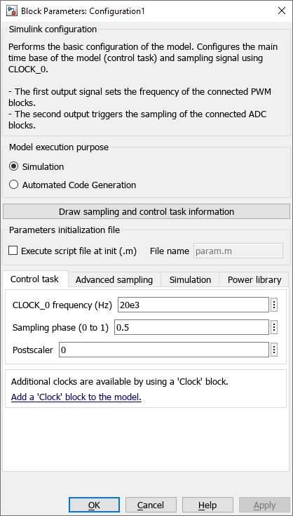
Simulink block
Signal specification
- The first output is the PWM clock signal and can be connected to the
>input of the PWM blocks to set their frequency to the CLK_0 frequency. - The second output is the sampling signal and must be connected to the
>input signal of all the ADC blocks of the model.

The simulation behavior of these signals is described in Simulation essentials with Simulink (PN135).
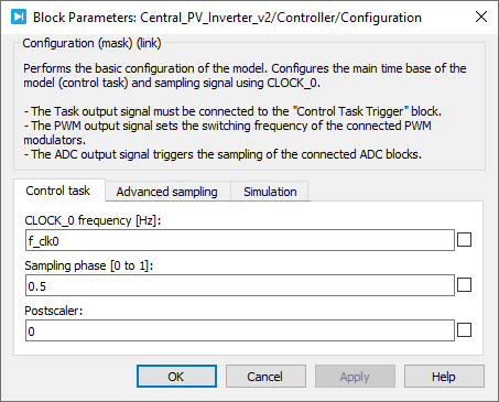
Control task parameters
- Clock frequency: sets the frequency of CLOCK_0, which is the time base for the ADC sampling, the control task execution, and the switching frequency of the connected PWM blocks.
- Sampling phase: sets the ADC sampling phase relative to CLOCK_0. The control task is executed right after the sampled values are available.
- Postscaler: divides the control task frequency such as \(\mathsf{control\ task\ frequency} \,\text{[Hz]} = \cfrac{\mathsf{CLOCK\_0\ frequency}}{\mathsf{postscaler}}\)
The postscaler parameter has no impact on the sampling frequency.
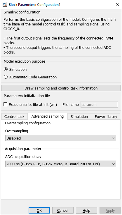
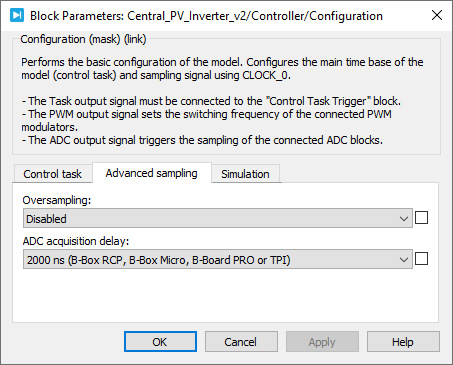
Advanced sampling parameters
- The oversampling parameter allows selecting selecting an oversampling ratio and having equidistant sample events (evenly distributed)
- The ADC acquisition delay corresponds to the acquisition and conversion process time of the ADC chip. This parameter can take multiples values because the B-Box analog frontend ADC chips are not the same as the ones embedded into B-Board PRO.
It can be set to:- 2000 ns (compatible with the B-Box RCP, B-Box Micro, B-Board PRO or TPI)
- 500 ns (compatible with the B-Box Micro, B-Board PRO or TPI)
Further documentation on how to benefit from the oversampling option is available in Oversampling (PN154).
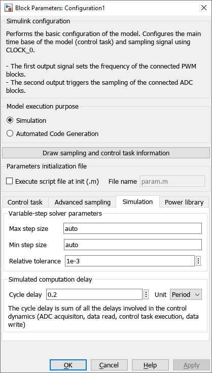
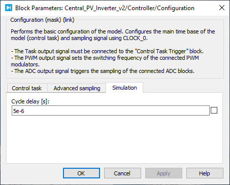
Simulation parameters
The cycle delay represents the total control execution time. As such, this sums up the delays involved in the control dynamics (ADC acquisition, data read, control task execution, data write). It is used in simulation mode only and serves to accurately model the time at which the PWM parameters are actually updated. This is part of the total actuation delay, whose modeling is required in order to accurately simulate control dynamics.
This value can be expressed in seconds (s) or as a ratio relative to the CLOCK_0 period (Period).
As the cycle delay cannot be anticipated before the control code is run on the target, this parameter must be measured during run time. To this end, Cockpit provides the necessary information in the Target timings tab.
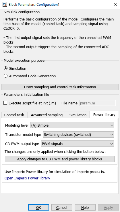
Power library
Please refer to the Getting started with Imperix Power library page.
PLECS block
Signal specification
- The
Taskoutput must be connected to the Control Task Trigger block. The Control Task Triggernominal base sample timemust be equal topostscaler/CLOCK_0frequency. - The
PWMclock signal must be connected to the>input of the PWM blocks to set their frequency to the CLOCK_0 frequency. - The
ADCclock output is the sampling signal. It must be connected to the>input signal of all the ADC blocks of the model.

The simulation behavior of these signals is described in Simulation essentials with PLECS (PN137)
Control task parameters
- CLOCK_0 frequency: sets the frequency of CLOCK_0, which is the time base for the ADC sampling, control task execution, and the switching frequency of the connected PWM blocks.
- Sampling phase: sets the ADC sampling phase relative to CLOCK_0. The control task is always executed right after the sampled values are available.
- Postscaler: divides the control task frequency such as \(\mathsf{control\ task\ frequency} \,\text{[Hz]} = \cfrac{\mathsf{CLOCK\_0\ frequency}}{\mathsf{postscaler}}\)
The postscaler parameter has no impact on the sampling frequency.
Advanced sampling parameters
- The oversampling parameter allows selecting selecting an oversampling ratio and having equidistant sample events (evenly distributed)
- The ADC acquisition delay corresponds to the acquisition and conversion process time of the ADC chip. This parameter can take multiples values because the B-Box analog frontend ADC chips are not the same as the ones embedded into B-Board PRO.
- It can be set to:
- 2000 ns (compatible with the B-Box RCP, B-Box Micro, B-Board PRO or TPI)
- 500 ns (compatible with the B-Box Micro, B-Board PRO or TPI) ADC acquisition delay can be set to:
Further documentation on how to benefit from the oversampling option is available in Oversampling (PN154).
Simulation parameters
The cycle delay represents the total control execution time. As such, this sums up the delays involved in the control dynamics (ADC acquisition, data read, control task execution, data write). It is used in simulation mode only and serves to accurately model the time at which the PWM parameters are actually updated. This is part of the total actuation delay, whose modelling is required in order to accurately simulate control dynamics.
This value can be expressed in seconds (s) or as a ratio relative to the CLOCK_0 period (Period).
As the cycle delay cannot be anticipated before the control code is run on the target, this parameter must be measured during run time. To this end, Cockpit provides the necessary information in the Timing info panel.
C++ functions
ConfigureMainInterrupt function. However, if oversampling is required, additional sampling instants can be configured using the ADC function Adc_SetUserOversampling() documented in ADC – Analog data acquisition.