Table of Contents
This page covers the configuration of the analog I/O channels located on the front-end of the B-Box 4. The B-Box 4 has 24 analog channels, all of which can be configured as either an input or an output, depending on the user code running on the controller. The following note documents the various configuration options of analog channels in input mode, supplemented by information on the operating principles of the B-Box 4 analog front-end.
Introduction
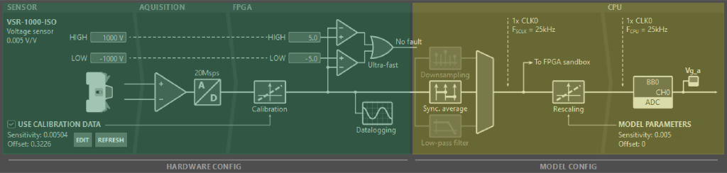
What constitutes an analog input channel from the user perspective, is actually a chain of hardware parts and fast software routines which produce the data that is available in the user’s control algorithm:
- The hardware section of the chain (in green below) consists of a sensor, external to the B-Box 4, connected to the analog I/O port. Inside of the B-Box 4 the input signal is captured by an analog-to-digital converter. The data is then fed through the FPGA to the hardware protection mechanism and for further processing.
- In the model section (in yellow below), the FPGA continues processing the data by sampling it down to the CPU clock rate, rescaling it into a meaningful quantity (based on the sensitivity of the whole chain, from the sensor to the acquired value) and transferring this data to the CPU memory in the shortest time possible.
Parts of this chain can be configured to fit the user’s setup:
- In terms of hardware configuration:
- Hardware protection mechanism safety limits and reaction time can be configured either through Cockpit or directly through the front panel screen menus of the B-Box 4.
- Sensor calibration options for compatible imperix devices can be configured through Cockpit
- The model section is configured based on the settings declared by the user in their control code, including:
- The direction of analog channels (input vs output)
- Selection and configuration of different sampling techniques
- Setting the cut-off frequency of the low-pass filter (if active)
- Configuring rescaling factors
How to configure analog front-end hardware
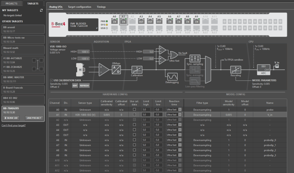
To access the analog I/O configuration of the B-Box 4 from Cockpit:
- Navigate over to the Cockpit Targets perspective by clicking on the TARGETS button in the left bar
- From the left bar, choose your device and select the Analog I/Os tab in the central area
- Read/modify the configuration of a given channel by selecting it in the virtual representation of the B-Box 4 front panel or in the table in the bottom half of the tab.
The same information is also available on the B-Box 4 front panel, through its LCD screen and rotary-push button. To access this information:
- Press the button, select the “Analog I/O” menu and enter it by pressing the button again
- Select the desired input channel and enter its menu
- Select one of the options, rotate the button to change its value and enter again to confirm your changes

Through the above methods, the following options can be configured:
- Options related to the hardware protection mechanism of the B-Box 4:
- Safety limit high – sets the limit in the range of [-10, +10]V
- Safety limit low – sets the limit in the range of [-10, +10]V
- Reaction time – sets the mechanism activation time to Ultra fast (\(0.8\mu s\)) or Fast (\(1.6\mu s\))
- If an auto-identification compatible imperix device was detected:
- Use calibration data – toggles applying the sensor calibration factors saved on the identified device
The sensor calibration factors can only be programmed through Cockpit, through the menu opened by clicking on the EDIT button in the sensor area of the channel diagram:
- Calibrated sensitivity [V/sensor unit] – compensates for the differences in real and nominal sensitivity
- Calibrated offset [sensor unit] – compensates any slight offset that might be present in the channel
Analog front-end operation and configuration
For a given control task rate \(F_{\text{CPU}}\), each ADC acquires samples at the largest possible multiple of \(F_{\text{CPU}}\) that is less than 20 MSps. The acquired samples are then fed into the:
- Hardware protection mechanism
- Oversample datalogger
- User-configurable FPGA and the CPU memory
The data are processed in parallel on all three paths. The following subsections explain the operating principles behind these systems and how to configure them.
Hardware protection mechanism (safety limits)
The B-Box 4 offers over-value and under-value protection for each channel. The protection mechanism was made software-independent since it was implemented in a non-editable FPGA section of the controller. However, the mechanism is configurable through its safety limits and two reaction time presets. As mentioned in the first section, these can be set either through Cockpit or through the B-Box 4 front panel screen.
Values acquired by the ADC that are higher than the designated HIGH threshold or lower than the LOW threshold of a given analog channel, trigger a safety limit fault. How quickly, depends on the reaction time setting, which can be:
- Ultra fast, equating to 4 samples or a total delay of at most \(0.8\mu s\)
- Fast, equating to 20 samples, or a total delay of at most \(1.6\mu s\)
Advice on how to choose safety limit thresholds is provided in Over-current and over-voltage protection.
Safety limit faults
Once a fault is declared:
- Output of PWM signals is immediately blocked
- The orange LED of the corresponding channel port lights up
- The fault is forwarded through BBOS to Cockpit
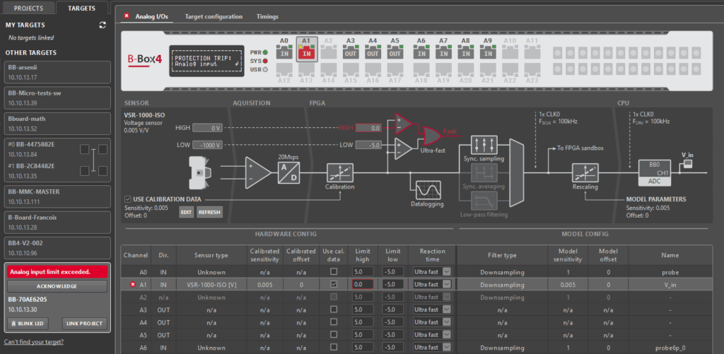
Both through Cockpit and the B-Box 4 front-panel screen the user can:
- Access information on which threshold was exceeded on which channel
- Acknowledge the safety limit fault
Safety limit faults can be acknowledged successfully only if the conditions that created the fault were removed. Whether it’s by relaxing the safety limits or by adjusting the operating procedure to stay within the systems’ safe operating area, it is strongly recommended to identify and understand why the fault happened before acknowledging it.
Oversample datalogger
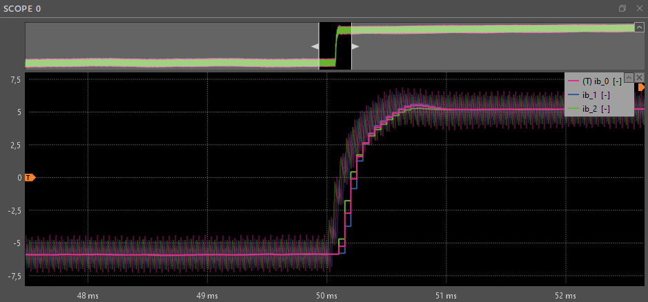
The Oversample datalogger saves the samples acquired by the ADC directly into the external RAM of the B-Box 4. The data are then made accessible in the Cockpit Scope Module through the Linux instance running on the controller’s supervisor CPU core. Unlike analog input signals in the CPU, oversampled signals are rescaled from the [-10, +10]V range, based on the ADC configuration , on the PC side, in Cockpit.
This allows the user to visualize data points that would otherwise not have been visible at the control sample rate and analyze phenomena like ripple currents and aliasing effects.
Analog front-end model-configurable section
Configuring analog channels from the user code starts by setting the channel direction. Any analog channel on the B-Box 4 for can be set either as an input or as an output, by configuring an ADC or DAC with the corresponding channel number. The information about the configured channel directions can be seen in the Analog I/Os tab of the corresponding B-Box 4 in Cockpit and in the front-panel screen menus.
Configuring the channel as an output activates the operational amplifiers that drive the I/O pins of that port. The amplifiers are controlled by the DAC chip and the DAC is updated with new values by the CPU as soon as possible after the end of the CPU control task. All DACs latch their values synchronously with a delay of up to one control task period. In this case, there are no further configurable options.
On the other hand, configuring an analog channel as an input activates a fast analog-to-digital converter (ADC) chip that feeds into several advanced, configurable mechanisms.
Analog input signals in the FPGA and CPU
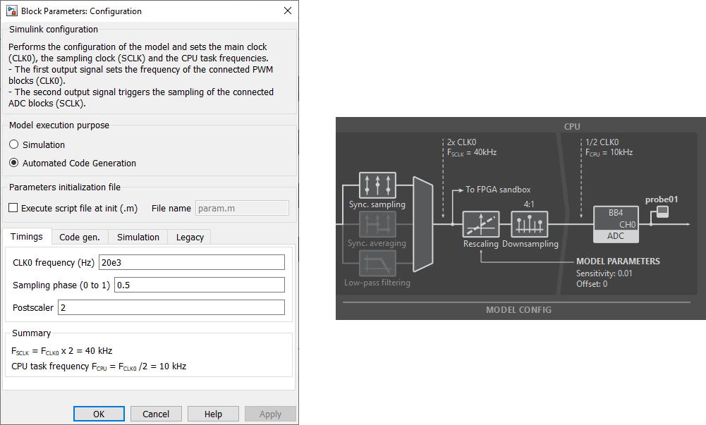
The samples acquired by the ADC are forwarded to be downsampled to \(F_{\text{SCLK}}\). The relationship between \(F_{\text{SCLK}}\), \(F_{\text{CPU}}\), and the B-Box 4 CLK0 is defined in the user code in the CONFIG block, through the Postscaler and Multiplier parameters.
Sampling the analog input signal down to \(F_{\text{SCLK}}\) is configurable for each analog input channel individually through ADC configuration in the user code. The resulting signal is available in the user-programmable section of the B-Box 4 FPGA and can be used to configure fast control schemes unbounded by the CPU control task rate. A more detailed guide on using the ADC signals available in the FPGA is available in the article on Getting started with FPGA control development.
Finally, before being made available to the CPU, the analog input signal is rescaled and then downsampled again, according to the configured Multiplier and Postscaler factors.
The rescaling is done to transform the acquired signal to meaningful physical quantities, since sensors output values in the [-10, +10]V range in order to be compatible with the analog input port of the B-Box 4. To do this, its values are divided by the sensitivity and shifted back by the offset declared during ADC configuration.
Choosing between sampling techniques on the B-Box 4
Three configurations are applicable to the B-Box 4:
- Synchronous sampling
- Synchronous averaging
- Low-pass filtering (always combined with Synchronous sampling)
Synchronous sampling works by taking the first sample out of all of the data points captured by the ADC, within one period of CLK0. This approach results in the smallest possible sampling delay but less robustness to noise and non-linearities.
Synchronous averaging, on the other hand, is a technique that takes all of the points captured within one or two periods of CLK0 and averages them. This results in an improved signal-to-noise ratio at the cost of a slightly higher sampling delay.
If a more aggressive attenuation in the high-frequency range is required, B-Box 4 also offers the option to apply a digital low-pass filter on the data captured by the ADC and then apply synchronous sampling on the resulting, smoothed waveform. The chosen filter cut-off frequency introduces a non-negligible group delay, which should be accounted for in the control algorithm. More information on the characteristics of the low-pass filter, can be found in the B-Box 4 datasheet.
The article on Advanced sampling techniques for power electronics gives a more detailed comparison between different sampling procedures.
Sensor auto-identification and calibration
The newest generation of imperix sensors and power modules comes with the capability to store information about themselves. This enables them to be identified automatically by the B-Box 4. The sensor information is stored on an EEPROM chip on the sensor and can be observed through Cockpit and the front panel screen of the B-Box 4.
A part of the information saved on the sensor is user-configurable. To correct any small deviations between the real sensor sensitivity and the factory configured one, as well as any slight offset the sensor may introduce into its readings, the user can input their own calibrated sensitivity and offset.
To configure sensor parameters from Cockpit, select the channel it is connected to in the Analog I/Os tab of the corresponding B-Box 4 and click on the EDIT button. In case a sensor was not found, or was added later, you can hit the REFRESH button to re-scan all of the analog inputs through 1-Wire.
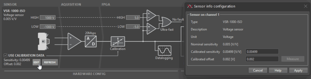
Clicking on the EDIT button opens up a Sensor info configuration window. The input Calibrated sensitivity and Calibrated offset will be saved on the sensor’s EEPROM upon clicking write. The calibration will be applied as long as the “Use calibration data” option is checked. The “Use calibration data” option is checked by default and can be changed either from the Analog I/Os tab in Cockpit or the B-Box 4 front-panel screen.
A more detailed overview of recommended calibration procedures is given in Sensor auto-identification on B-Box 4.
Overview of all front-end configuration options
The following table provides a complete overview of all front-end related configuration options, where they can be configured from and to which values:
| Configuration option | Configurable from | Possible values | Comment |
| Calibrated sensor sensitivity | Cockpit Analog I/Os tab | Real values with precision of up to 6 decimal places | Values interpreted in [V/sensor unit] |
| Calibrated sensor offset | Cockpit Analog I/Os tab | Real values with precision of up to 6 decimal places | Values interpreted in [sensor unit] |
| Use sensor calibration data | Cockpit Analog I/Os tab | True, False | Option only available for auto-detection-compatible imperix sensors. |
| Safety limit high | Cockpit Analog I/Os tab and B-Box 4 front-panel | [-10, 10]V with 0.1V precision | Accuracy ± 1 % m.v. ± 10 mV |
| Safety limit low | Cockpit Analog I/Os tab and B-Box 4 front-panel | [-10, 10]V with 0.1V precision | Accuracy ± 1 % m.v. ± 10 mV |
| Protection mechanism reaction time | Cockpit Analog I/Os tab and B-Box 4 front-panel | Ultra fast, Fast | Max delay \(0.8\mu s\) and \(1.6\mu s\), respectively |
| Analog channel direction | The ADC and DAC block in the user code | In, Out | |
| Analog input acquisition mode | The ADC block in the user code | Sync. sampling, Sync. averaging | Sync. averaging can be set to work over 1 and 2 periods of CLK0 |
| Analog input Low-pass filter | The ADC block in the user code | Off, 0.5kHz, 1kHz, 1.6kHz, 2.5kHz, 4kHz, 6.4kHz, 8kHz, 10kHz, 16kHz, 20kHz, 32kHz, 40kHz, 64kHz, 80kHz, 100kHz | Low-pass filtering is always paired with Sync. sampling |