Synchronous reference frame (SRF) PLL
Table of Contents
This note provides insights into the operating principle of a synchronous reference frame PLL (SRF PLL), also known as DQ-type PLL. An implementation of an SRF PLL is found in the ACG SDK as the DQ-type PLL block and in the CPP SDK in the API folder of the template project. For a different type of PLL, please refer to the page on the SOGI PLL. Also, note that this page will focus on the three-phase implementation of the PLL. Single phase PLL are discussed in Fictive axis emulation (FAE) for single-phase inverter. Finally, typical use cases for DQ-type PLLs are listed at the end of the page.
What is a synchronous reference frame PLL?
Most of today’s grid-tied power converters aim to control active and reactive power flow. Accurate phase tracking systems are then required to synchronize the controlled currents or voltages with the utility grid voltages. Many grid-synchronization techniques exist and an extensive review of the possible implementations can be found in the Grid synchronization methods page or in [1].
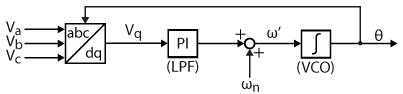
A synchronous reference frame PLL is a basic type of phase-locked loop based on the Park transform. In a nutshell, the SRF PLL is built using a Park transformation that acts as a phase detector, a low-pass filter (LPF) usually in the form of a PI regulator, and a voltage-controlled oscillator (VCO) typically made from an integrator [2]. The objective of this PLL is then to minimize either the direct or quadrature axis reference voltage. This will then ensure that the phase angle of the rotating reference frame of the park transformation matches the phase angle of the utility grid voltage vector [3].
The general principle of an SRF PLL is given below:
SRF PLL implementation
As mentioned, the idea behind the synchronous reference frame PLL is to detect the phase angle by synchronizing the rotating frame reference of the PLL to the utility grid voltages, ensuring that \(V_q = 0\). The structure proposed for the SRF-PLL is shown below. The park transform and the PI controller are very classic. Additionally, \(V_q\) is normalized so that the tuning of the PI controller does not depend on the amplitude of the grid voltage. Finally, the integrator is based on the forward Euler method, with the only specificity being that the output is wrapped between \([0; 2\pi[\).
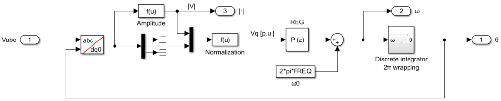
Moreover, when the estimated frequency from the PLL is used for applications beyond the PLL itself, it is highly recommended to filter the frequency estimation using a low-pass filter with a cutoff frequency of around 15 Hz. This ensures a smooth and reliable frequency estimation for stable performance in different applications.
Regarding the dynamic performances of the SRF PLL, it is difficult to get both fast-tracking and good filtering characteristics. Indeed, as stated in [2], a trade-off between these two characteristics is necessary when tuning the control loop parameters. For a PLL with better dynamic performance, one can look into the page: SOGI PLL.
Software implementation
Simulink model
PLECS model
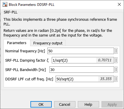
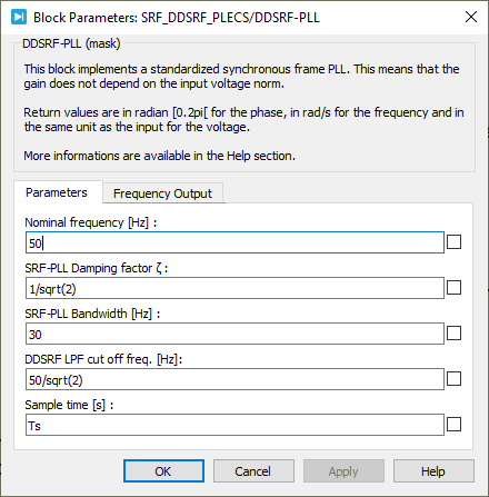
The provided Simulink and PLECS model implements both the SRF-PLL and DDSRF-PLL using the ACG SDK for simulation and code generation.
Simulink
PLECS
Tuning of SRF PLL
To complete the implementation of the SRF PLL, the PI controller gains have to be determined. This can be achieved by linearizing the control loop [4] and deriving the following transfer function.
$$P(s) = \frac{\hat{\theta}}{\psi}(s) = \frac{2\zeta\omega_c s + \omega_c^2}{s^2+2\zeta\omega_c s + \omega_c^2} \quad \quad \text{with} \quad \quad K_p = 2\zeta\omega_c \quad \text{ and } \quad K_i = \omega_c^2$$
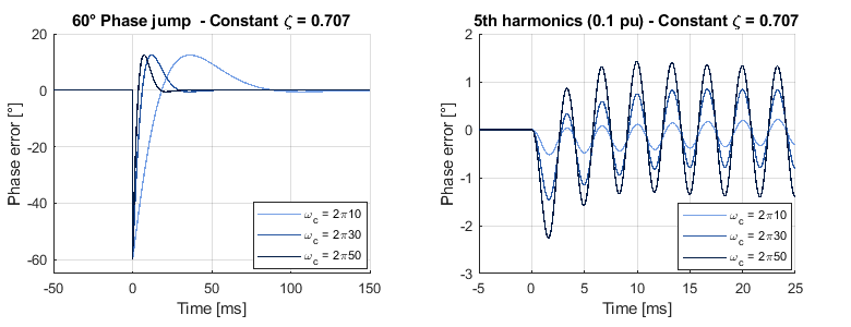
Where \(\psi\) represents a phase disturbance, \(\hat{\theta}\) is the estimated phase, \(\zeta\) is the damping factor, and \(\omega_c\) is the PLL bandwidth. To achieve a good trade-off between settling time and overshoot, a commonly used damping factor is \(\zeta = \frac{1}{\sqrt{2}}\). On the other hand, the bandwidth parameter, \(\omega_c\), determines the settling time of the PLL and its disturbance rejection capability. A higher \(\omega_c\) results in a shorter settling time but increases sensitivity to disturbances. Therefore, \(\omega_c\) should be chosen based on the quality of the grid voltage. A typical value for real grids is approximately \(\omega_c \approx 2 \pi 30\) rad/s.
The figures below illustrate the impact of \(\omega_c\) during a phase jump and when 5th harmonic distortion is present in the grid voltage.
Experimental results
Experimental results and detailed comparisons with other PLLs are available on the Grid synchronization methods page.
Going further : Double Decoupled Synchronous Reference Frame (DDSRF) PLL
Thanks to its simplicity and performance under nominal conditions, the SRF-PLL has become the PLL of choice for applications where robustness against disturbances is not required. However, in the presence of unbalance in the grid voltage, an oscillating term at twice the fundamental frequency appears after the Park transform. The DDSRF-PLL effectively addresses this issue by using a decoupling network to separate the positive and negative sequence components, ensuring accurate detection even under unbalanced voltages.
Decoupling
The idea behind this decoupling is to generate a signal that mimics the parasitic signal at twice the fundamental frequency, using known parameters or those obtained through filtering. This generated signal is then subtracted from the main signal to achieve decoupling of the positive and negative sequence voltages. The mathematical development of this decoupling process is shown below.
Implementation of the DDSRF-PLL
The algorithm for decoupling the positive and negative sequences is implemented as shown below. A decoupling network for both sequences is added after the Park transform ensuring that only the positive sequence is used in the SRF-PLL.
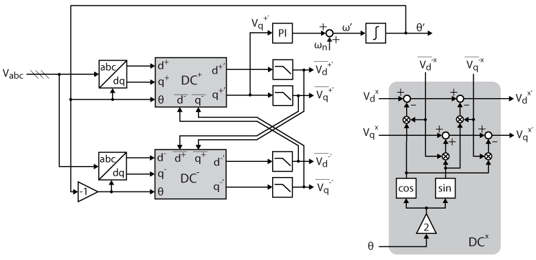
Where the \(DC^x\) blocks implement the mathematics developed above to achieve decoupled voltages in the dq reference frame. The complete implementation of the DDSRF-PLL on Simulink is shown below
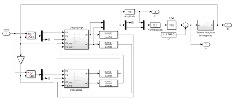
The corresponding simulink file can be downloaded above, in the same file as the SRF-PLL. Experimental results and detailed comparisons with other PLLs are available on the Grid synchronization methods page.
Academic references
[1] M. Boyra and J. Thomas, “A review on synchronization methods for grid-connected three-phase VSC under unbalanced and distorted conditions,” in Proc. EPE Conf., Birmingham, 2011.
[2] S.-K. Chung, “A phase tracking system for three-phase utility interface inverters,” IEEE Transactions on Power Electronics, vol. 15, no. 3, May 2000.
[3] L. Arruda and B. Silva, S.M.and Cardoso Filho, “PLL structures for utility connected systems,” in 2001 IEEE Industry Applications Society 36th Annual Meeting (IAS’01), Chicago, USA, Sep./Oct. 30–4, 2001
[4] P. Rodriguez, J. Pou, J. Bergas, J. I. Candela, R. P. Burgos and D. Boroyevich, “Decoupled Double Synchronous Reference Frame PLL for Power Converters Control,” in IEEE Transactions on Power Electronics, vol. 22, no. 2, March 2007.
Use case examples
As introduced above, phase-locked loops are used in most of today’s grid-tied power converters. Here are a few examples of such converters: