SOGI PLL
Table of Contents
This note covers the operating principles of a Second-Order Generalized Integrators (SOGI) PLL and presents a possible implementation for digital power electronics controllers. Its implementation in Simulink is available for download.
What is a SOGI PLL?
Second-order Generalized Integrators (SOGI) have recently been proposed for use as phase detectors [2] and positive-sequence voltage detectors [4], especially within PLL structures found in grid-tie power inverters.
Numerous grid synchronization techniques exist, featuring various performance, objectives, and complexity. An extensive review of possible implementations is proposed in [1]. Among them, many rely on a phase detector that offers some immunity to voltage waveform distortions (harmonics and/or unbalances). This immunity, related to the employed filtering techniques, is often a difficult trade-off with other expectations expressed in terms of dynamic performance (phase and/or amplitude tracking).
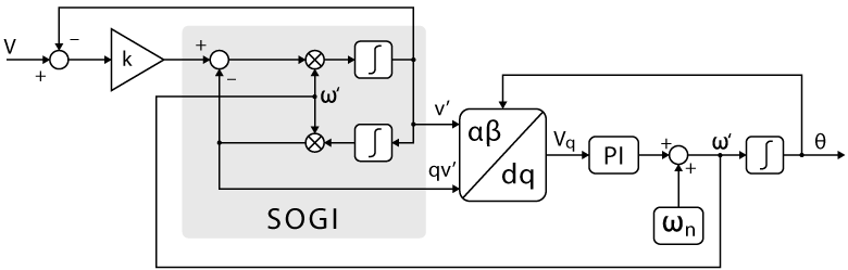
SOGI structures are mainly composed of two filter types. First, a band-pass filter with no phase delay at the fundamental frequency is used for the estimation of the phase voltage v’. Secondly, a low pass filter with 90° phase delay is used for the estimation of the quadrature-shifted signal qv’. Therefore, SOGI structures have the attractive benefit of providing simultaneous access to both the filtered output as well as a quadrature-shifted version of the same output (α and β axes). As such, they allow for an easy implementation that can fit that of conventional SRF-PLLs (using the Park transform as phase detector).
The general principle of the SOGI-based PLL is given below:
Transfer functions of the SOGI
Based on the preceding diagram, the subsequent transfer functions can be derived :
$$D(s) = \frac{v’}{v}(s) = \frac{k \omega’s}{s^2+k\omega’s+\omega’^2} \quad \quad \quad Q(s) = \frac{qv’}{v}(s) = \frac{k\omega’^2}{s^2+k\omega’s+\omega’^2} $$
Where \(\omega ‘\) represents the estimated fundamental frequency and \(k\) the damping factor of the SOGI block. These transfer functions are displayed below in the frequency domain to illustrate the impact of these parameters (here with \(\omega ‘\) = 50Hz).
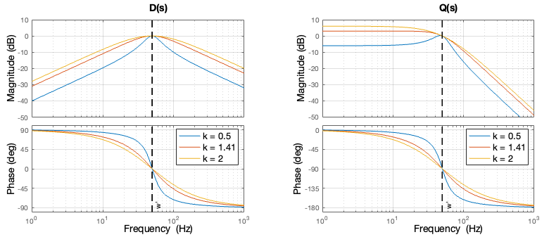
An examination of the above transfer functions reveals that the parameter \(\omega ‘\) centers the transfer function of the filters, while the parameter \(k\) plays a significant role in adjusting the filter’s bandwidth.
It is also worth noting that the damping factor \(k\) does not alter the behavior of the SOGI at the frequency \(\omega ‘\). Consequently, a lower \(k\) value enhances frequency selectivity but slows down the response to voltage changes. Therefore, a trade-off between transient response and attenuation of distorsions must be made. A commonly adopted tuning is \(k = \sqrt{2}\) (equivalent to \(k = 2\zeta = 2\frac{1}{\sqrt{2}}\))[4], with \(\zeta\) representing the damping ratio for a second-order system.
SOGI PLL digital implementation
The discrete-time implementation of a SOGI-based PLL is mostly dependent on the selected approach for the discretization of the two integrators embedded within the SOGI itself.
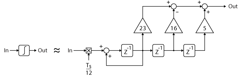
Reference [2] analyzes the impact of the selected discretization approach (namely forward-Euler, backward-Euler, Tustin, ZOH, etc.) on the stability of the overall SOGI subsystem. The article concludes on the suitability of the backward-Euler integrators. Alternatively, reference [3] also compares various possible techniques, concluding on the superiority of the so-called Third-order Integrator method, thanks to a lower residual ripple on the frequency and amplitude signals. The corresponding integrator implementation is shown below:
Single-phase implementation
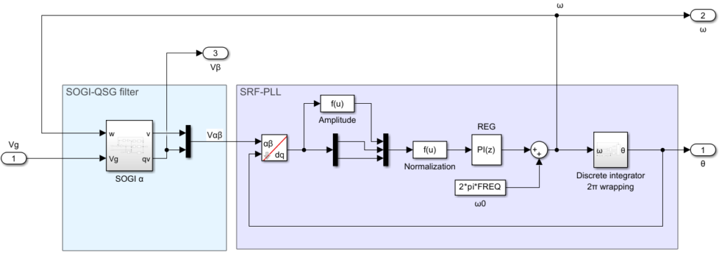
The structure of the proposed single-phase SOGI-type PLL is shown below:
Three-phase implementation
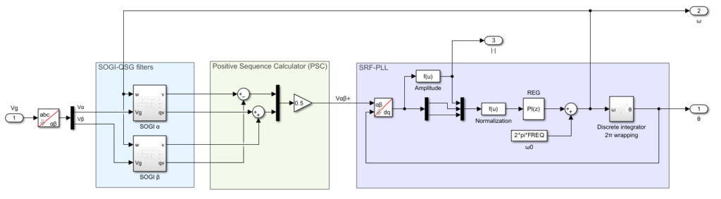
The somewhat equivalent of the above-presented structure for three-phase systems is given below. In this case, two SOGIs are used, not only to take benefit from their filtering characteristics but also to combine their outputs so as to detect the positive sequence exclusively. This approach, designated DSOGI-PLL by their authors [4], provides excellent immunity against grid voltage unbalances.
Software implementation
The implementations on Simulink and PLECS of the presented PLLs are available in the models provided below:
Simulink model
PLECS model
These Simulink and PLECS subsystems are masked, so that the corresponding parameters can be easily accessed and modified as follow.
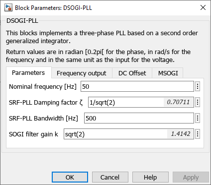
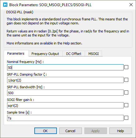
These implementations can be easily integrated into control algorithms developed using imperix ACG SDK toolbox.
Regarding the tuning of the SRF-PLL, suggested parameters are provided on the SRF-PLL page. It’s important to note that when used with SOGIs, the bandwidth can be increased to \(2 \pi 500\) rad/s (instead of \(2 \pi 30\) rad/s). This enhancement is feasible because the SOGIs naturally filter out high frequencies, resulting in less noise in the signal entering the SRF-PLL.
Experimental results
The following graph provides an experimental comparison between a DQ-PLL and the DSOGI-PLL. The DSOGI-PLL provides superior immunity against unbalanced and distorted grid voltages over the standard DQ-PLL:
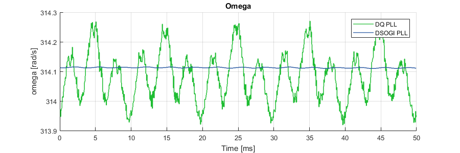
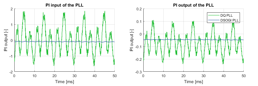
Further experimental results and detailed comparisons with other PLLs are available on the Grid synchronization methods page.
Going further: SOGI PLL under disturbed grid conditions
In real-world conditions, the grid voltage waveform may be distorted due to various disturbances, presenting a significant challenge for accurate phase and frequency estimation. The most prevalent sources of these disturbances include harmonic distortion and DC offset.
DC offset rejection
If a DC offset is present in the measured voltage, it is not filtered by \(Q(s)\) since the latter is of low-pass type. Consequently, the offset is also transferred to the quadrature signal qv′ and enters the SRF-PLL. This continuous term is then shifted to \(2 \omega\) through the Park transformation, resulting in an oscillating term at twice the grid frequency in \(V_q\). Given that the PI controller is unable to fully attenuate a non-continuous term, this oscillation is further propagated to the frequency and phase estimations.
To address this issue, the SOGI block can be modified so that the low-pass filter generating the quadrature signal, \(Q(s)\), is replaced with a band-pass filter with the same characteristics at the fundamental frequency. The corresponding block diagram is provided below and can be easily replicated in Simulink or PLECS. A similar implementation is described in [5].
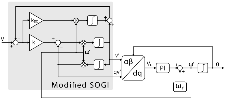
The new \(D(s)\) and \(Q(s)\) transfer functions are displayed below in the frequency domain to visualize the impact of the modified SOGI and the parameter \(k_{DC}\).
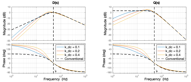
With the modification of the SOGI block, the filter for the quadrature signal,\(Q(s)\), has been transformed into a band-pass filter, thereby enabling the filtering of a DC offset on the quadrature signal.
Harmonic distortion rejection (MSOGI-PLL)
In a SOGI block, the attenuation of low-order harmonic distortions typically ranges between -10dB and -20dB for harmonics of order less than 10th (at a given parameter \(k = \sqrt{2}\)). In certain applications, this level of attenuation may prove insufficient.
In order to selectively attenuate certain harmonics, a cross-feedback network composed of multiple SOGIs can be introduced, each tuned to the selected frequencies. This solution is referred to as the Multiple SOGI-PLL (MSOGI-PLL). It is very effective for estimating the positive sequence component under disturbed conditions. The corresponding block diagram is provided below and can be easily replicated in Simulink or PLECS. A similar implementation is described in [6].
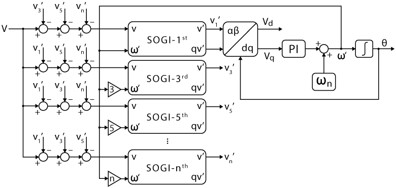
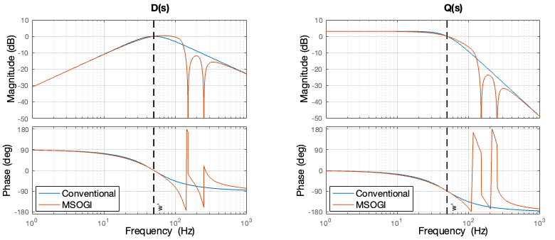
Moreover, to maintain the same bandwidth for each SOGI, the gain \(k\) is divided by the order of the corresponding harmonic to ensure an equal \(k \omega′\) factor for each filter, even if they are tuned to different frequencies. An example of transfer functions of the MSOGI is presented below, where the 3rd and 5th harmonics are significantly attenuated.
It is worth noting that, in this configuration, DC offset removal has not been implemented. Should this feature be necessary, only the SOGI designated for the fundamental frequency requires DC offset removal.
Experimental results of this type of SOGIs and detailed comparisons with other PLLs are available on the Grid synchronization methods page.
Academic references
[1] M. Boyra and J. Thomas, “A review on synchronization methods for grid-connected three-phase VSC under unbalanced and distorted conditions,” in Proc. EPE Conf., Birmingham, 2011.
[2] M. Ciobotaru, R. Teodorescu and F. Blaabjerg, “A new single-phase PLL structure based on a second-order generalized integrator,” in Proc. PESC Conf., Rhodos, June 2006.
[3] F.J. Rodríguez, E. Bueno, M. Aredes, L.G.B. Rolim, F.A.S. Neves and M.C. Cavalcanti, “Discrete-time
implementation of second-order generalized integrators for grid converters,” in Proc. IECON Conf.,
Orlando, Nov. 2008.
[4] P. Rodríguez, R. Teodorescu, I. Candela, A. V. Timbus, M. Liserre and F. Blaabjerg, “New positive-sequence voltage detector for grid synchronization of power converters under faulty grid conditions,” in Proc. PESC Conf, Jeju, 2006.
[5] M. Xie, H. Wen, C. Zhu and Y. Yang, “DC Offset Rejection Improvement in Single-Phase SOGI-PLL Algorithms: Methods Review and Experimental Evaluation,” in IEEE Access, Vol. 5, pp. 12810-12819, 2017.
[6] P. Rodríguez, A. Luna, I. Candela, R. Mujal, R. Teodorescu and F. Blaabjerg, “Multiresonant Frequency-Locked Loop for Grid Synchronization of Power Converters Under Distorted Grid Conditions,” in IEEE Trans. on Pow. Elec., Vol. 58, No. 1, Jan. 2011.